Friday, December 30, 2011

Power Supply Preparation

While I'm debugging the VC Trigger Generator, and waiting for my MTA headers to arrive, I've been getting things together for my power supply panel. 


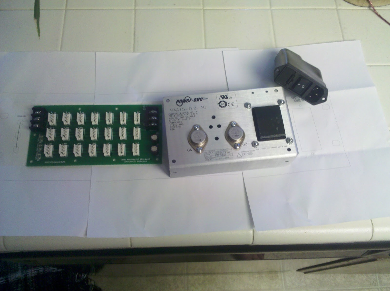
I used David's power panel as a starting point - and am using the same power supply and switch/fuse unit, so those elements I could copy over. The one I'm making is using a MOTM-960 power distribution board, and is a full 3U rack panel, rather than a subrack panel.  I've also added 3 jacks for a ground connection, so I can connect power supplies, or even use them for applying an S-Trigger signals.

I printed out the panel just to make sure everything seemed to fit. Seems good, so I've ordered the panel (plus panels for a VCA, a VCF, and two VCOs) today.

The power supply I'm using is the HAA15-0.8-AG.  I'm somewhat second-guessing myself, if I shouldn't have used the HBB15-1.5-AG, to get 1.5 amps on each rail, rather than only 0.8 amps.  But, the Synthasystem isn't too power intensive, and I'll probably end up with a couple anyhow.  Of course, I could run the supply at +/-12V (and adjust the modules for that) to get 1.0 amps, but +/-15V is much more practical for me, as everything else I have (or am even considering building) runs at +/-15V.

More details when the panel comes in and I start putting this together!  The power supply setup was the thing that scared/confused me the most when I was getting started in modular synths, so fingers crossed that this all comes together fine.

Wednesday, December 28, 2011

Trigger Generator Panel Wiring

I've now wired up nearly everything on the VC Trigger Generator.  I used heatshrink tubing around all of the terminals on the switches, pots, and the LED. I'm so glad I picked this heatshrink up from Small Bear... it actually, you know, shrinks in response to heat?  As opposed to the Radio Shack garbage I had been using, which probably requires reciting a magical incantation to work decently.


After taking the picture, I wired up the LED too.  I attached a wire to the Trig/Gate input jack as well, but it isn't connected to anything yet, as I ran out of MTA headers.  (I should have a big box of MTA headers in the mail tomorrow or Friday.)  On the pushbutton switches, I should've soldered the wire at a 90-degree angle, rather than straight out; it puts them just at 1" from the panels, so I can't screw the PCB down all the way onto the standoffs.

I ended up getting everything put together (besides that one input), and powered it up.  Unfortunately, it isn't working!  I think the UJT is fried, but I'm looking into this further. I'll write up more details on all of this later, once I have a better grasp of the problem.

Monday, December 26, 2011

Temporary Power Adapter

Since I don't yet have everything I need to build up my power supply (more on this later!), I decided that I'd test the modules on my Dotcom system. So, I've started to make a few Dotcom to MOTM power adapters on little pieces of veroboard.


Not too pretty, but pretty simple! I'm going to put some Plasti-Dip or liquid electrical tape over the board, for insulation. I won't be running the SynthaSystem from this power configuration, but it will be enough for testing.  (Plus, these will come in handy for some CGS and other builds I'm doing, which I'll be putting into my Dotcom cabinets.) I'm tempted, though, to get a bunch of little PCBs done up for this.

Sunday, December 25, 2011

Sorry, Dremel!

Sorry, Dremel!  I didn't need you.  I didn't need to go to the hardware store either.

I was really anxious to get the standoffs working in the Voltage Follower and S&H.  Unfortunately I don't have any sort of grinder, or even a metal file, here.  So, I figured I'd try sandpaper. Slower than a snail. Then, it occurred to me that I could get a grinder bit for my drill. But, did I really feel like going to the store?  It dawned on me that maybe I could do something in between...


I doubled over a piece of sandpaper, and then rolled it up. Opened the chuck all the way, stuck it in, and cranked down the chuck. Voila!  I ran it in reverse, so that the edge of the paper wouldn't catch.  It took one piece of sandpaper per standoff, and was rather awkward, but it worked, and cost me nothing.


Not the greatest photo, but hopefully you can see that the standoff is shaved down a fair amount.  And now, it fits!!

I just need to remember to fix the FPD files!!

Saturday, December 24, 2011

Panel Parts & MTAs

I started building up the panels a bit today. Unfortunately, I thought I had a bunch of 2-terminal MTA plugs, but I was nearly out!  So, more stuff I need from Mouser!

Also, FedEx failed to bring my Small Bear order as scheduled... so I'll have to wait until Tuesday (ugh!) to get my order of wire (I'm nearly out), heatshrink tubing, and knobs.


So far I'm liking using these banana jacks. As you can see, the 4 trigger outputs on the VC Trigger Generator are multed together... not really necessary for banana systems, but I wanted to keep the layout.  I could wire up the pots and switches, but I'm waiting for the heatshrink tubing... wanted to do as nice a job on this as possible.

Friday, December 23, 2011

Panels Arrive!

Well, my first three panels from Front Panel Express arrived!  Never ordered any panels from them before, so it was a bit of a new experience.  They look nice - I did them without infill, and like the result.


As you can see, I added a couple of holes for switches on the Sample & Hold, along with "INT" indicators for the internal noise signal.  Thankfully, the holes for the banana jacks are perfect!


Unfortunately, however, I didn't get the jacks far enough away from the holes for the standoffs - bummer!  You can see how close the nut is in the picture of the back of the Voltage Follower. Same problem on the Sample & Hold. So, I will definitely have to move the standoff holes for future panels!  (The VC Trigger Generator seems fine, though!)  Maybe someone will get me a dremel tool for Xmas, so I can grind down the nut and/or standoff a bit.

At least there's a bit of good news, and that is that everything fits fine around the new switches on the S&H!  The jacks look a bit close to the text, but with the little bit of play, I can space them out appropriately.

Thursday, December 22, 2011

Voltage Controlled Oscillator PCB

And, finally, the Voltage Controlled Oscillator PCB!  (Two of them, actually!)  The is the bigger "A" model oscillator in the Synthasystem. Feature-wise it is a pretty typical oscillator and has sine, saw, triangle, and pulse outputs. Each output has an attenuator, which is a bit atypical. There's both coarse and fine controls, along with exponential (1V/Oct) inputs, one of which is attenuated. In addition, there's a sync/reset input, pulse width control, and a pulse width modulation input.


A rather big board, for sure!  Lots of transistors and trimpots.  There's a few more "gotchas" with this one than the other builds.  First, note that I haven't installed the ICs yet: there's 4 LM741 OpAmps, and one THAT340 for the exponential converter.  There will also be a 1k thermistor/tempco sitting over the THAT340, but I don't want to instal that until everything else is ready.  Also, there's pads for two SSM2210s, but I've used unmatched transistor pairs: apparently they should be fine. (Note that later Synthasystems even used unmatched pairs for the critical exponential converter!)

There's a few 0.1% tolerance resistors that you can see at the far end of the picture... there's two for summing the VC input, and four more around the expo converter.  You can also see the styrene capacitor. The pad spacing on this board revision is pretty small, so I've mounted it with one lead coming down from the top, along the side.  Hopefully this will be fine!  (It looked cleaner than trying to position it some other way.)

You'll notice space for a trimmer up front there: it is actually supposed to be empty. There's two spots next to each other, for the triangle shaper. You're supposed to use the right one, and jumper a pair of (marked) pads on the left one. If the oscillator doesn't perform well, then you're supposed to swap the trimpot and the jumper. Hopefully that won't be necessary!

There's a couple other trimpots that have been omitted too.  One is the 1V/Oct calibration, which I'm instead moving to the front panel as one of the panel-mount trimpots (there's an MTA header for it, so no flying wires from pads in the middle of the PCB).

The other is for the scale of the 3rd VC input. There's a few options for this: I've opted to use a 200k pot on the front panel (it is a feature I like), but you could use the trimpot, the panel-mount trimpot (again, there's an MTA header), or make it a fixed scale!  There's an associated scaling resistor... for my 200k pot, I'm using a 22k resistor (as suggested in the BOM) - it would be the same for any equivalent trimpot. If you're using a fixed scale, choose the resistor and then jumper two of the marked pads under the trimpot.

Wednesday, December 21, 2011

Some Build Notes & Thoughts

Just thought I'd jot down a few thoughts and remarks that I have about populating these PCBs.  For the most part, the builds have all gone really well. Just a couple of joints that I've had to re-flow, and some minor component issues.


My lead bending tool (Mouser 5166-801) is - as always - a lifesaver. Don't ever leave home without one.

For soldering, I have a Weller WTCPT with a PTA7 tip. Solder-wise, I am using Kester 331 on the board, and Kester 245 everywhere else (pots, etc.). How I ever survived growing up with those terrible Radio Shack soldering pencils and solder is beyond me. I am so glad I shelled out the cash for this stuff at the beginning of this year.

The Kester 331 is water-soluble, so after (nearly) every day of soldering, I wash the board, with distilled water and a toothbrush. The 245 doesn't need cleaning. (I suppose the 331 doesn't absolutely need cleaning either, but it makes it both nicer to look at, and work with.

I've also got a desoldering pump (Digikey K412-ND). I don't use it much, but it seems to work fine.

There's nothing special about the rest of my tool set!

I am waiting on an IC pin straightener from Futurlec, though... it should make inserting the ICs into the sockets a lot nicer... most ICs usually come with the pins at a slight angle... bending them against the table with your fingers isn't ideal.

Anyhow, as I mentioned, only a few components are giving me any trouble. And, those are the Murata MLCCs - the fancy, blue ceramic caps. Not sure why I picked these specifically, but they've got bends in the leads so that they sort of snap into the board. Unfortunately, the coating (just around the legs) will sometimes crack when you're putting them in place. (Happens if you try and straighten the leads too.) It doesn't seem to be an issue, electrically... but it is still annoying. I'll probably go with Kemet MLCCs in the future... they're cheaper, too.

Tuesday, December 20, 2011

Panel-Mount Trimpots

A few of the Synthasystem modules feature panel-mounted trimpots. On the VCO, I'll be installing these trimpots for the 1V/Oct adjustment trimmer. The Ring Modulator and the Tuner/Monitor also have these: presumably they're all settings that may need to be readjusted more often than your typical trimpot.


The PCB sets come with these neat little trimmer chicklet PCBs. The actual trimmers go inside these panel-mount housings from Bournes. They look like blue 1/4" jacks, with a trimmer screw in the middle (tough to get a pic, sorry). I just popped the trimmers (Bournes 3600 series) into the housing (Bournes H-83P), and then solder it onto the chicklet. Anyhow, for wiring there's 3 through-hole pads at the back of the PCB to attach wires. These should make the wiring a lot simpler!

Monday, December 19, 2011

Voltage Controlled Filter PCB

The voltage controlled filter! As I mentioned before, this uses a different topology than the Steiner Synthacon filter. I'm no expert in filters (trying to learn!), but apparently it has some unique elements. Also, it will operate in low-pass, band-pass, or high-pass modes (there's a switch on the front panel).


Note the 0.1% tolerance input summing resistors. I've also used a 200k trimpot instead of 250k, as on the VCA.  1.2u electrolytic caps are unavailable, so I've used tantalum ones here instead: a little pricier, but not a big deal for just three of them.  And, as before, I've used the discrete transistor pairs: a totally discrete VCF!

Sunday, December 18, 2011

VC Trigger Generator PCB

The VC Trigger Generator is a bit like an LFO, I suppose, but for generating triggers (these are the S-Triggers I was writing about earlier).  It has pads to allow for V-Triggers too; I've installed all of those parts, for completeness (they may help for any debugging, too!), but I'll be using the S-Triggers.


Yep, that's a LOT of transistors! 17 of them! (And only 2 are for the V-Trigger add-ons.)  Two SSM2210s have been replaced with discrete pairs. Note also the 2N4891 on the left (the little tin can)... hard to find, but I got 10 from Nikko in the UK. That should be plenty for what I may eventually build: they're only used here, the Sequencer, and the S&H.

There's a 2M resistor printed on the board; it should be 100k. It is well-documented on the schematic, etc., but just make sure you take note of it.

Another resistor is listed as "SELECT" - this is the resistor for the LED. I put a 1k resistor in there, which should be fine for the yellow LED I plan on using (Mouser 78-TLHY5401). There's not many LEDs in the Synthasystem: just here, the Peak Selector, and the Sequencer... this is the only one where you need to select a resistor value, though. In case you don't remember:

RLED = (Vcc - Vf) / If , where:
Vcc is the source voltage (here, per the schematic, +12V)
Vf is the forward voltage drop of the LED (look this up on the datasheet or Mouser page, 2.4V for mine)
If is the forward current of the LED (look this up on the datasheet or Mouser page, 10mA for mine)

So mine calculates out as (12 - 2.4) / .01 = 9.6 / .01 = 960R, and I rounded up to 1k.

Saturday, December 17, 2011

VCA/Mixer PCB

The Synthasystem VCA doubles as a mixer with its 3 inputs, which is a nice feature. It is a relatively easy build.  This is one of the modules that uses the external power regulation PCB: it connects to the board via the 5-pin MTA-100 header on the right.


The two sets of input summing resistors are all 0.1% tolerance. The BOM calls for the CV Reject trimmer to be 250k, but I've used a 200k as there's no 250k with this footprint. It should work fine, and David's Synthasystem pages mention this. The final thing to note is that I've used a pair of discrete BC500B transistors, rather than a SSM2210 chip. The pads are labeled to allow for discrete transistors; just be sure to check the datasheet to position them correctly.

Originally I planned to use the SSM2210s, but at $10 each (and given the number in the system), it didn't seem too practical. Plus, apparently they aren't really crucial either; in some later Synthasystems, even the transistors in the VCOs weren't matched.  I will still use a THAT340 chip in the VCO exponential converter (which is temperature controlled too), but I think that's the only place I'll use a matched pair.

Friday, December 16, 2011

HF Correction PCB

The HF Correction PCB is a small add-on PCB for the VCO. It basically just helps improve the oscillator's tracking at high frequencies.


It is clearly not a very exciting board, but obviously it isn't supposed to be.  Two of the connections on the MTA go to different points on the VCO board. The third is ground, which I'll probably just tie to something on the power regulation board.

Anyhow, I just ordered panels for the Voltage Follower, Sample & Hold, and Trigger Generator. They should arrive by the end of next week. Hopefully everything is fine for my banana jack conversions!!

Thursday, December 15, 2011

Triggers

The original Synthasystem - like early units from Moog, Korg, and Yamaha - used S-Triggers for their gate signals.  Most other (and modern) synthesizers use V-Triggers.  There's a more in-depth discussion here, but basically... V-Triggers are at 0V while at rest, and +5V when active.  S-Triggers, on the other hand, short to ground when active.  Theoretically S-Triggers are supposed to be at +5V or something when at rest, but in my experience it can be floating too.

The way I see it, both systems have their advantages and disadvantages.  V-Triggers allow you to use the same sort of signal everywhere: everything is a voltage!  Plus, most V-Trigger systems use comparators on the input, so you don't have to use an explicit gate signal.  S-Triggers, though, allow you to passively OR gate signals without any problems, and the signal can be created passively.


It is easy to generate an S-Trigger signal.  I've made a few shorted 1/4" plugs for my MS-10. With banana jacks that isn't as easy, though you can (of course) plug an input into a ground jack.  That being said, however, the Synthasystem's VC Trigger Generator makes trigger generation quite simple (manual, LFO, gated, etc.).

If you're still afraid of S-Triggers, let it be known that the Synthasystem PCBs have added circuitry to allow for V-Triggers as well. They come off of different headers as well, so if you need to switch, it is easy.  The only exception is the sequencer, but there's an additional board to provide the conversions.

I'll be going with the S-Triggers, mostly since it think it would be fun to have a modular using those. I am adding the components for the V-Triggers (for completeness), but won't be using them.  (Though they could be useful if debugging.)  So that I don't ever confuse myself, I'll also be using red banana jacks for all of the trigger inputs & outputs.

Wednesday, December 14, 2011

Sample & Hold PCB

The Sample & Hold is another dual module in the Synthasystem.  While it doesn't have a built-in clock (it requires external triggers), each S&H circuit has its own random voltage generator, which is a nice feature. Any external source can also be used.


As you can see, this uses the rather rare 2N4891 UJTs ($10 for each of those tiny metal cans!!), though some other UJTs may work. Take note, too, that good quality caps are needed here - I've used styrene.

Since I'm using banana jacks, this module becomes a bit more complicated.  The unit is designed for switching jacks on the signal inputs: when no plug is inserted, the input is the internal noise generator.  I'll just be adding a couple switches to the panel to take care of it.  Besides the switches, signal input, trigger input, and output, each S&H unit also has an output level pot.

Tuesday, December 13, 2011

Voltage Follower PCB

The Voltage Follower is probably the most simple module in the Synthasystem.  In fact, it is actually two units in one module. "Voltage follower" is yet another name for slew, lag, glide, portamento, etc.  The power regulation is all on the PCB.


As before, I've omitted the Doepfer power header and LEDs... I won't mention this in the future.  I also haven't installed the LM741s or the heatsinks. The panel components are pretty simple: a pot and two jacks (input/output) for each of the two followers in the unit.

While I'm at it, I'll mention that all of the boards are set up for using MTA100 connectors. I'm comfortable with these, having used them on my Dotcom system.  The "T"-handle tool is a bit of a pain, but it has grown on me. The MTAs are probably a little bit overkill for a banana jack system (and some of that panel wiring can be fun), but it certainly can't hurt.

Monday, December 12, 2011

Component Notes

You can read extensive info on David's site about component notes... rare parts, substituted parts, etc.  I'll cover just the basics when I discuss those modules.  In the meantime, I thought I'd mention a few things I'm doing, plus some general observations.

I decided to use 1% metal film resistors everywhere, except where 0.1% tolerance ones are called for. I tend to do this for all of my projects... it makes ordering easier, and I can generally read them better.  Though I'm starting out with just a few modules (2x VCO, VCF, VCA, S&H, Trigger Generator, and Voltage Follower), I made up a bill of materials for my 10-row "dream" Synthasystem (ahem!).  I ordered all of the resistors, diodes, rare parts, etc. for that.  The caps and most of the ICs I'll then order as I need them (same for the panel parts).


One thing that really caught my attention while putting together the BOM was how few different active components were involved!  In fact, only 13 of them, and three of them are used exclusively in the power regulation.  There's also only a handful of opamps in the system (all LM741, except for a CA3140 in the Selective Inverter).  Most everything is handled by transistors and diodes - it'll be a bit of a learning experience for me, as I'm unfamiliar with the non-opamp versions of many of these circuits. (Obviously you don't need to understand them to build them, but I'm trying to do both.)

There's quite a few SSM2210s in the system, but I'll likely be replacing these with pairs BC550B transistors.  They aren't in critical places; a THAT340 is used for the expo converter in the VCO.

Sunday, December 11, 2011

Power Regulation PCBs

The Synthasystem runs off of a rather odd power configuration: +12V/-10V. Thankfully, David has made provisions on his PCBs for regulators, so you can run the system off of +/-12V or +/-15V, and each module will take care of its own power requirements. (Both MOTM/Blacet and Doepfer power headers are available too.)  There's a pair of trimpots to set each voltage correctly.

On the smaller modules the power regulation is directly on the PCB.  Most of the larger modules, however, use a generic power regulation PCB.  I'd recommend labeling the PCBs for what module they're used with - there's a couple of resistors and caps which change (or are omitted) depending on the power filtering requirements of the module.


It is a really simple build, and the power regulation sections on the smaller boards are similar.  I'll be adding heatsinks to the LM317 and LM337 later. You'll note that I've omitted the Doepfer power header, and two LEDs.  The LEDs are only really there to give some load if you're testing and configuring it without any external load.  Actually, I intended to add them, but I goofed and forgot them in my giant Mouser order; I installed the associated resistors in case I ever decide to add them.

Saturday, December 10, 2011

Gone Bananas

David's panels designs (FPD) are set up for the EuroRack format. I suppose this makes sense, given that it is one of the most popular modular synth formats these days.  Plus, the original modules were quite near 3U in height.  Generally, I am not a fan of the EuroRack format, but the designs here are far from your typical EuroRack configurations... they're very classic, well-labeled, and don't seem cramped. In addition, they're all multiples of 7hp in width.

The only thing that still had me wary was the 3.5mm jacks. I know the original used 'em, and I know some of you love 'em... but to me they feel so flimsy, and I really can't stand them for anything besides headphones.  I also didn't want to go with yet another format... my Dotcom system uses 1/4" jacks, and the Best of CGS I plan on building will use banana jacks.  So... why not go bananas?!  And that is what I decided to do.


There's only a few "gotchas" with using bananas in the Synthasystem, due to switching jacks.  But, those are really only on the VCA, Sample & Hold, and Envelope Generator.  I'll get into this further as I write about these specific modules (and my builds) later.

I also updated all of David's FPD files to use banana jacks.  There's a number of places in the system that use multed outputs, which aren't really needed for banana jacks, but I decided to keep them since I really liked the designs (and in some cases they give symmetry).  There wasn't much I needed to change otherwise - mostly just a few spacing issues. I haven't ordered any panels yet, though... so fingers crossed!!

Friday, December 9, 2011

Starting a Synthasystem!

Time for more modular irresponsibility!  As if I didn't have enough in-progress MU modules that I am building, and 3 panels for a Best Of CGS synth on the way, I decided to add something to the mix.

The Steiner-Parker Synthasystem!  

These were originally designed & sold in the late 1970s and early 1980s.  From what I can tell it is a somewhat obscure system... the near lack of online information about it has always put it in the same category as other obscure early modulars like the E-mu, Polyfusion, and Aries (at least to me).

Though also rare, the Synthacon is probably the more well-known Steiner synth - if only due to the popularity of the filter topography in many DIY (and other) modules, with its LP, BP, and HP inputs.  But everyone has surely heard the Synthasystem!  The first sounds heard in Apocalypse Now (the helicopter, before The Doors song kicks in) was done on a Synthasystem - by Nyle Steiner himself - along with many other parts of the soundtrack.

Recently the Synthasystem was resurrected by David Ingebretsen, who originally started to build one from Nyle's schematics years ago.  He got back in touch with Nyle and has produced PCBs of the circuits, along with panel artwork and extensive documentation.  The system looks great!  And it sounds great too, from the YouTube videos David has posted, including this one of Nyle playing it:

Ultimately, after looking over the modules, and discussing it a bit with David, I decided that I needed to jump aboard!

David's site can be found here: http://user.xmission.com/~dingebre/Synthasystem.html

I got my first set of PCBs the other week, and my initial Mouser order yesterday, so the madness has officially begun!

I'll use this blog to document my build of the system, along with my various thoughts and insights.