Sunday, February 26, 2012

Switching Things Up

I switched out my Electroswitch rotary switches on the VCF with some Alpha ones.  They have a much nicer feel & response (at least to me).


Since they don't have a way to set the max number of positions, I wired one up for band-pass, the 6 to the left as low-pass, and the 6 to the right as high-pass.  (The final position at the bottom I left disconnected.)  I also used liquid electrical tape since heat-shrink wouldn't work so great for this.  Didn't turn out super pretty, but it does the job (and the heat-shrink is pretty much overkill, but I am doing it anyways!).

Oh, and here's a bit of a preview of the Triple EG!


This was a total beast to build!  It is a dense and heavy module!  Can't wait to test it (I was missing some MTA connectors for power, but they should be here Wednesday.)

Monday, February 13, 2012

Phase Shifter complete!

And the phase shifter is now complete, too!


A fair amount of op-amps in there!  It is a 4-stage, 720-degree phaser. There's a wet/dry knob to control a mix of the original signal & the phase shifted signal, which is ideal for effects.  I only tested it lightly, but it seemed that the frequency knob didn't do much above 2:00 - perhaps it was just due to the setting of the original waveform, as it clearly did a lot to the signal before it got to 2:00!  There's a VC input for this too, but I haven't played with it yet - since it is summed with the frequency knob, however, it should work just fine.

Sunday, February 12, 2012

Ring Modulator complete!

And, the Ring Modulator has also been completed!


This uses an MC1495 IC (four quadrant multiplier), which is certainly a more frequently encountered solution (with a variety of different chips & circuits) than the diode "ring" design.

It has a couple of trimpots, for the Signal Null and Carrier Null... they're pretty simple to set.  Obviously the one is on the front panel, but I'm not sure why, i.e. if it needs more frequent adjustment or what.  There's also a pot to adjust the mix of original signal to modulated signal, which could prove interesting to play with.

While I'm at it, let me admonish the reader to watch out for those blue plastic panel-mount trimpot assemblies.  The threads are very prone to being stripped, and, as they're plastic (and have some flashing), they're quite easy to strip if you're not careful (and sometimes even if you are careful... oops!).

And finally, there's a Mult/Square switch.  In the multiply position, it acts as a standard ring modulator.  However, in the squared position it sends the signal input to the carrier input too... honestly, I'm not sure why this wasn't originally implemented with a normalled jack (as they're used in other situations in the Synthasystem), but no matter - for me it'll save a banana cable!  Theoretically I think it is supposed to double the frequency, but instead it just seems to change the signal a bit.  I honestly haven't played around with this a whole lot (mostly just setting the trimmers), so I'm sure there's quite a bit to discover.

Saturday, February 11, 2012

Peak Selector complete!

Here's the completed Peak Selector module.


Another fairly simple build. I now feel a lot more comfortable wiring up LEDs. This is basically just a comparator that outputs an S-Trigger (and lights an LED) whenever the input exceeds the set threshold.  However, it isn't done with OpAmps, so (to me) it is a bit more confusing, circuit-wise.  It has a minimum on-time, which seems useful, but means that if you want to feed it noise, you'll have to do so through a sample & hold or something - otherwise the output will be on all the time.

In the meantime, I also ordered a panel for the Triple EG yesterday... I tried to order all the panel parts too, but I'm afraid that I forgot some of the MTA connectors for the power - aaah!!  There's always one thing I forget whenever I place a Mouser order...

Friday, February 10, 2012

Noise Generator complete!

Here's the completed Noise Generator module!


Simple panel assembly; just a pair of jacks, a level pot, and a white/pink switch.  The next one I do will have the pot to go between white and pink.  Sounds great!  And works like a charm.

Thursday, February 9, 2012

Rack-Mount Power Supply

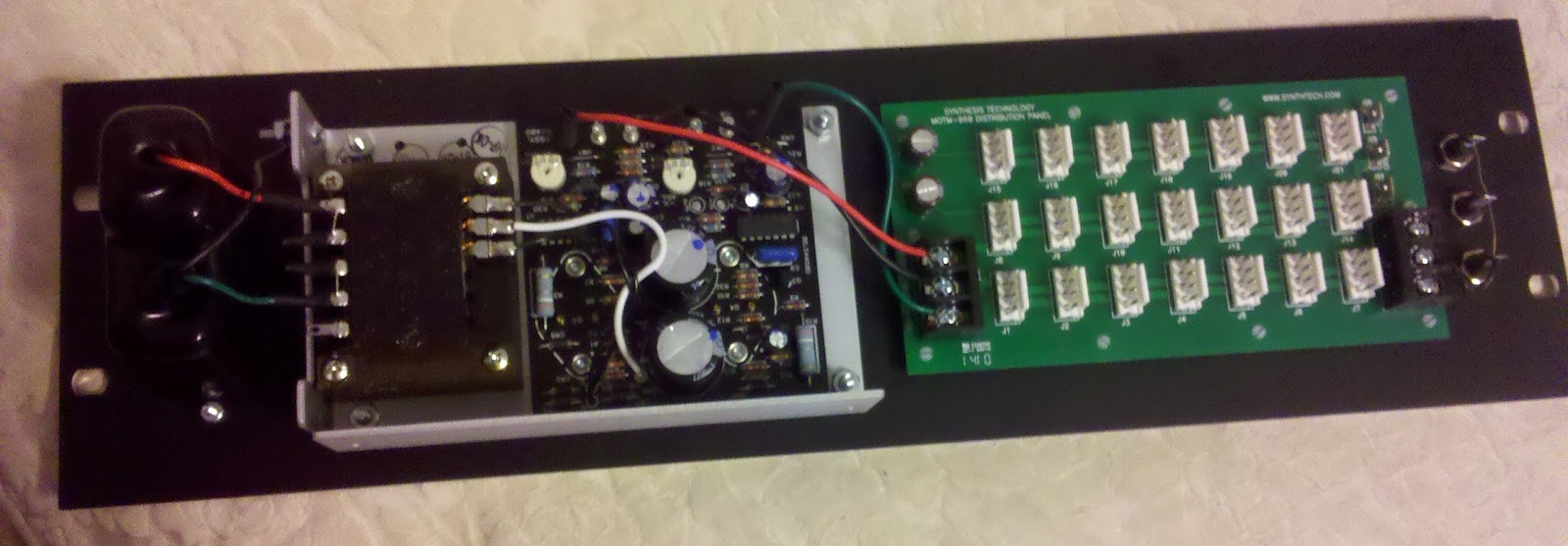
Unrelated to the Synthasystem, I just had a bit of an "accident" with some liquid electrical tape. Oops! What a mess!  Anyhow, ... here's the rack-mount power supply I've been working on.  If my Synthasystem reaches the size that I secretly hope it will, I'll have four of these.  But for now, one will be fine!


Sorry for the horrible pics!  This is using a PowerOne HAA15-0.8-AG PSU, an MOTM-960 distro-board, a few banana jacks (for a common ground), and Schurter plug/switch/fuse/etc. (KD13.1101.151, 4303.2906, and 0859.0074)  If only these things were more constantly in-stock at Mouser... ugh.

Anyhow, I made a full 3U high panel to hold all of these, based on David Ingebretsen's PSU panels. This uses the same PSU and switch/plug/fuse panel, but not the Blacet distro boards.  I've added 3 banana-jacks for ground, attached to the distro-board.  This is essential for many banana-based systems: individual modules aren't connected to a common ground via the PSU (i.e. different/multiple PSUs) and the path-cables (being bananas) don't include ground. So, there's a need to connect the ground of all power supplies.

Most of the connections are pretty self-explanatory... power supply common output goes to ground on the distro board, and then get brought out to the banana jacks.  +/- outputs on the PSU go to their respective terminals on the distro board as well.  The PSU inputs are all documented in the datasheet that comes with the PowerOne supply, and then the earth connection from the plug unit gets bolted to the PSU.  Since I want it to run +/- 15V, I cut the two jumpers that are marked on the PSU PCB.  Plugged it in and the house didn't burn down!  Measured the outputs and they are +15.02V and -15.02V - yay!

In the meantime I've also finished the Noise, Peak Selector, Ring Modulator, and Phase Shifter modules, and will post those soon.  I still need to order the panels for the Triple EG and Frequency Divider... unfortunately, I'm still working out an ideal rotary switch (need for the Frequency Divider).

Tuesday, February 7, 2012

ENVDT PCB

And here's the third board from the Triple EG, the ENVDT.  Its envelope is a bit more complicated than the others; it has the attack/delay switch like the 2nd EG, but it is more of an Attack/Release envelope (it lacks the "Duration Level", i.e. Sustain of the others).  The duration time can be controlled either by the incoming trigger's length, or a pot.


Though more complex than the ENVDL boards, it is a bit more straightforward since there's only one variant.  On both this and the ENVDL boards, I've used tantalum caps in place of the impossible-to-find 1.2u and 3.9u electrolytics.  Also, on this board, I went ahead and used the modified values for R22 and R28, as described in the build docs.

Monday, February 6, 2012

ENVDL PCBs

The Synthasystem's Triple Envelope Generator uses three PCBs (not counting the power regulation one).  The first two EGs use these ENVDL boards, while the third uses the ENVDT board.

I'll get into the specifics of the EG in more detail at a later time (i.e. when I finish the module), but basically, the first two EGs are nearly ADSR, although Decay and Release are controlled by the same knob.  With a short trigger input, they act as AD envelopes.  Both of them also have an overall level control, Damping and "Quathin" switches (for slightly different behaviors), and switches to combine their output with the third EG.

The second EG also features a switch to change the Attack control to be a delay control (with a near instantaneous attack).


Here's the two boards.  As you can see, I've marked them "1" and "2", and crossed out the parts to be omitted for the two variants.  Perhaps it isn't super pretty, but I find it useful when stuffing them, and checking them over later.  One of the MTA connectors is for a connection to the ENVDT board for the switchable combined 1+3 and 2+3 EG outputs.

I'll cover the ENVDT board tomorrow.  In the meantime, I finished up my power supply over the weekend (just a couple tweaks before I present it here), and the panels for the Noise, Phase Shifter, Ring Modulator, and Peak Selector are scheduled to arrive on Wednesday!

Wednesday, February 1, 2012

Frequency Divider PCB

The Synthasystem Frequency Divider is a rather unique and interesting module.  It produces four user-selectable divisions of an input signal and sends them to a mixer with level controls for each division, and a master level control.  Each divider outputs a square wave, so you could use it for audio and CV signals, creating suboctaves, staircases, etc.  And it will work as a clock divider too, with alternate inputs and outputs for S-Triggers.

This sort of module was pretty rare for modulars in the 1970s. In fact, as far as I can tell, the only other manufacturer to come close was Polyfusion, with their model 2090 Octave Divider.  I don't know much about the 2090, but I've seen a schematic and it is based around the 4024 ripple counter, and has seven fixed division outputs; I'm not even sure if it was intended more for CV or audio. There was also a frequency divider from Blacet, but I'm not sure what features were on the original (or even what it looked like). John Blacet had an article describing a simple 4024-based frequency divider in Vol. 1 Issue 3 of Synapse in 1976; I'm guessing his own was an expanded version, and perhaps only available as a kit. Other than those, I am not aware of anything from the 1970s (Moog, Buchla, Aries, ARP, E-μ, Serge, etc.) that did any sort of clock divisions or suboctaves (besides using a sequential switch for basic clock divisions).

Anyhow, enough archaeological discussions!


Yeah, that's a lot of parts!  No CMOS here, just a ton of transistors and diodes.  I've omitted three resistors and a transistor at the bottom center - they're for the the S-Trig to V-Trig converter on the output, and I've omitted it for the same reason discussed previously regarding the Peak Selector (i.e. to keep the output floating when off).

I'm holding off on ordering the panels until I get a couple of Alpha rotary switches from Mouser.  I'd like something a bit different from the Electroswitch ones, so I want to check these out before I get the panel made.